A Latch is one of the most basic memory circuits. It stores data based on the control of an Enable (E) signal.
- D (Data input): The value to be stored.
- E (Enable): Controls when data can be written.
- Q (Output): Holds the stored value.
When E = 1, the latch is transparent, and Q follows the input D.
When E = 0, the latch holds its previous state.
Block Diagram
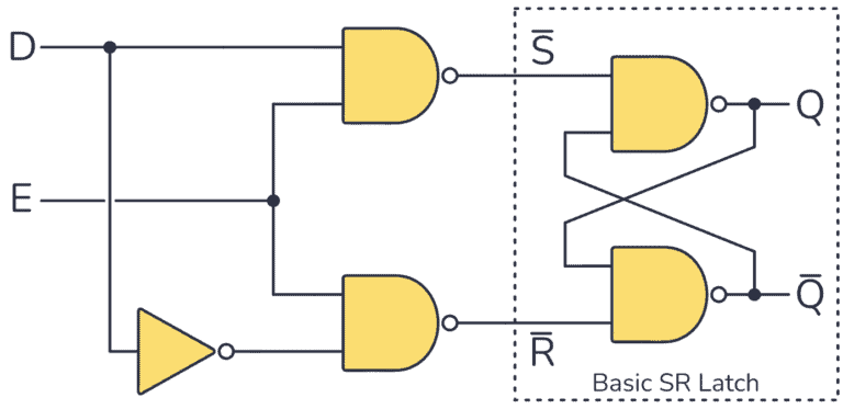
D is the data input, and E is the enable, when the E is on. Data is written and stored into Q.
Verilog Implementation
Behavioral Model
module D_Latch (
    input D, E,
    output reg Q
);

always @(*) begin
    if (E)
        Q = D;   // When enabled, Q follows D
    // When E = 0, Q retains its previous value
end

endmodule