A D Flip-Flop is formed by combining two latches:
- Master latch
- Slave latch
It allows data to be written only on a clock edge, making it more stable than a latch.
Types
- Positive Edge Triggered: Data is written into
Qwhen the clock transitions from0 → 1. - Negative Edge Triggered: Data is written into
Qwhen the clock transitions from1 → 0.
🔑 Difference from Latch:
- A latch is transparent whenever enabled.
- A flip-flop updates only on a clock edge, preventing glitches and improving stability.
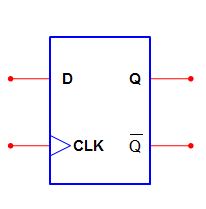
Block Diagrams
Positive Edge Trigger
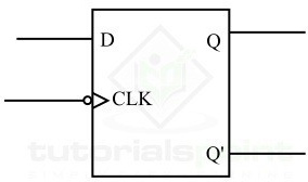
Negative Edge Trigger
Verilog Implementation
Flip-flops should always be written at the behavioral level.
Basic D Flip-Flop
module DFF (
    input Din,
    input clk,      // Clock signal
    output reg Dout // reg since used in always block
);

always @(posedge clk) begin // use negedge for negative edge
    Dout <= Din;
end

endmodule
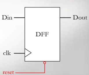
With Reset
Since the initial stored value is unknown, reset is often included.
Synchronous Reset
- Reset is checked only on the active clock edge.
module DFF_sync_reset (
    input clk,
    input reset,       // active-low reset
    input [7:0] Din,
    output reg [7:0] Dout
);

always @(posedge clk) begin
    if (!reset)
        Dout <= 8'd0;
    else
        Dout <= Din;
end

endmodule
Asynchronous Reset
- Reset is effective immediately, independent of clock.
module DFF_async_reset (
    input clk,
    input reset,       // active-low reset
    input [7:0] Din,
    output reg [7:0] Dout
);

always @(posedge clk or negedge reset) begin
    if (!reset) //when the reset signal goes from `1` to `0`
        Dout <= 8'd0;
    else
        Dout <= Din;
end

endmodule
With Write Enable
To prevent accidental overwrites, a w_en input is added.
Data is written only if w_en = 1 at the active clock edge.
module DFF_wen_async_reset (
    input clk,
    input reset,       // active-low reset
    input w_en,        // write enable
    input [7:0] Din,
    output reg [7:0] Dout
);

always @(posedge clk or negedge reset) begin
    if (!reset) // when reset signal goes from `1` to `0`
        Dout <= 8'd0;
    else if (w_en)
        Dout <= Din;
end

endmodule