An accumulator is a simple sequential circuit that repeatedly adds input values to its previously stored result.
It makes use of a memory element such as a D Flip Flop to store the intermediate sum.
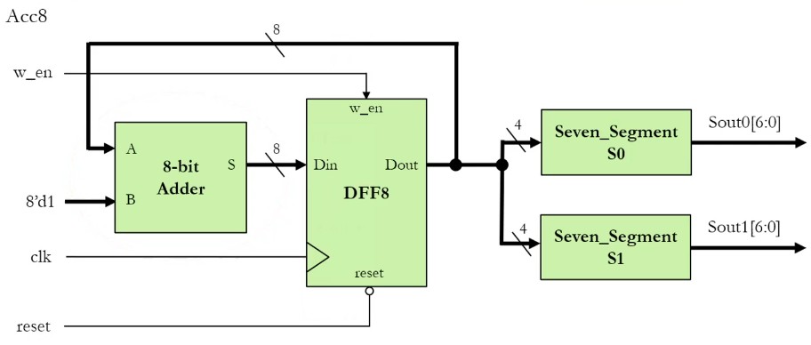
Block Diagram
-
reset: Clears the stored value to0at startup. -
w_en: Write enable – prevents accidental overwriting. -
On each positive clock edge, the stored value (
Dout) is incremented and written back.
Verilog Implementation
8-bit D Flip Flop
module DFF8(Din, clk, reset, w_en, Dout);

input [7:0] Din;
input clk, reset, w_en;
output reg [7:0] Dout;

always @(posedge clk or negedge reset) begin
    if (!reset) begin
        Dout <= 8'd0;
    end
    else if (w_en) begin
        Dout <= Din;
    end
end

endmodule
8-bit Adder
Using two 4-Bit Carry-Lookahead Adder:
module CLA8(A, B, C_in, C_out, S);
    input [7:0] A, B;
    input C_in;

    output [7:0] S;
    output C_out;

    wire CLAOut_0;

    // Lower 4-bit CLA
    CLA4 CLA4_0 (
        .C_in(C_in),
        .A(A[3:0]),
        .B(B[3:0]),
        .S(S[3:0]),
        .C_out(CLAOut_0)
    );

    // Upper 4-bit CLA
    CLA4 CLA4_1 (
        .C_in(CLAOut_0),
        .A(A[7:4]),
        .B(B[7:4]),
        .S(S[7:4]),
        .C_out(C_out)
    );

endmodule
Accumulator
Using CLA
module ACC8(w_en, clk, reset, Sout_0, Sout_1);
    input w_en, clk, reset;
    output [6:0] Sout_0, Sout_1;

    wire [7:0] Dout, Din;

    // Incrementer: Dout + 1 -> Din
    CLA8 CLA8_0 (
        .A(Dout),
        .B(8'd1),
        .C_in(1'b0),
        .C_out(),
        .S(Din)
    );

    // Register (accumulator)
    DFF8 DFF8_0 (
        .Din(Din),
        .clk(clk),
        .reset(reset),
        .w_en(w_en),
        .Dout(Dout)
    );

    // Seven-segment display
    Seven_Segment S0 (
        .Din(Dout[3:0]),
        .Dout(Sout_0)
    );

    Seven_Segment S1 (
        .Din(Dout[7:4]),
        .Dout(Sout_1)
    );

endmodule
Using + Operator
module ACC8(w_en, clk, reset, Sout_0, Sout_1);
    input w_en, clk, reset;
    output [6:0] Sout_0, Sout_1;

    wire [7:0] Dout, Din;

    assign Din = Dout + 8'd1;

    // Register (accumulator)
    DFF8 DFF8_0 (
        .Din(Din),
        .clk(clk),
        .reset(reset),
        .w_en(w_en),
        .Dout(Dout)
    );

    // Seven-segment display
    Seven_Segment S0 (
        .Din(Dout[3:0]),
        .Dout(Sout_0)
    );

    Seven_Segment S1 (
        .Din(Dout[7:4]),
        .Dout(Sout_1)
    );

endmodule