An 8-bit priority encoder can be designed using two 4-bit priority encoders and a multiplexer.
- The input is divided into two groups of 4 bits each:
- Lower 4 bits → handled by PENC4 (P0)
- Upper 4 bits → handled by PENC4 (P1)
- A multiplexer then selects the output of the higher-priority group.
How It Works
- If any bit in the upper nibble (Din[7:4]) is
1, it has higher priority than the lower nibble. Dout[2]indicates whether the upper nibble is active.- The lower 2 bits of
Doutcome from the selected 4-bit encoder.
Block Diagram
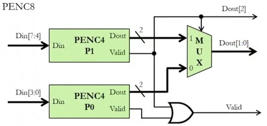
Dout[2]= 1 when upper block (PENC4 for Din[7:4]) is active.
Verilog Implementation
module PENC8(Din, Dout, Valid);
    input  [7:0] Din;
    output [2:0] Dout;
    output       Valid;

    wire [1:0] Dout_0, Dout_1;
    wire       Valid_0, Valid_1;

    // Instantiate two 4-bit priority encoders
    PENC4 P0(.Din(Din[3:0]), .Dout(Dout_0), .Valid(Valid_0));
    PENC4 P1(.Din(Din[7:4]), .Dout(Dout_1), .Valid(Valid_1));

    // Determine final output
    assign Dout[2]   = Valid_1;                      // MSB indicates upper block
    assign Dout[1:0] = (Valid_1) ? Dout_1 : Dout_0;  // Select correct block
    assign Valid     = Valid_0 | Valid_1;            // OR of both valid signals
endmodule