The USB Host Controller is part of the chipset (or CPU). It appears to the system as a PCI device. USB 2.0 controllers usually use the companion controller architecture.
PCI Configuration Addressing
PCI devices are identified using:
- Bus (B)
- Device (D)
- Function (F)
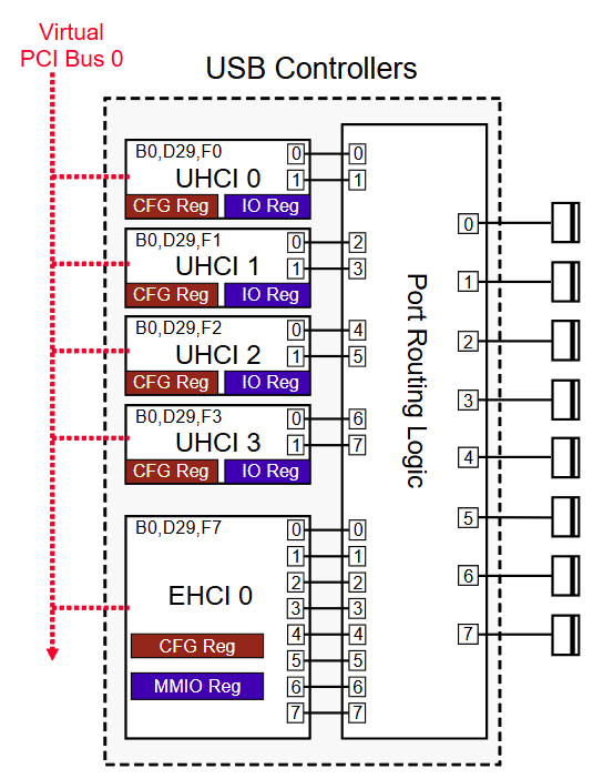
Example Mapping
| Controller | PCI Address |
|---|---|
| UHCI 0 | B0:D29:F0 |
| UHCI 1 | B0:D29:F1 |
| UHCI 2 | B0:D29:F2 |
| UHCI 3 | B0:D29:F3 |
| EHCI 0 | B0:D29:F7 |
Key Idea
- All controllers share:
- Same Bus (0)
- Same Device (29)
- Each controller is distinguished by a unique Function number
Register Types
Each USB host controller has two main types of registers:
1. PCI Configuration Registers
- Accessed via PCI configuration software (Configuration Space)
- Used to:
- Identify device capabilities (Vendor ID, Device ID, Class Code)
- Assign address space for:
- Memory-mapped I/O (MMIO) → EHCI
- I/O-mapped registers → UHCI
- Support features like:
- Power Management Capability (PMC)
- Interrupt Handling (INTx or MSI)
- Advanced Error Reporting
| Key Config Register | Offset | Purpose |
|---|---|---|
| Vendor ID / Device ID | 0x00–0x03 |
Identify the controller |
| Command | 0x04 |
Enable I/O, memory, bus master |
| Status | 0x06 |
Report error flags, capabilities |
| BAR (Base Address Register) | 0x10+ |
Map controller registers into address space |
| Interrupt Line / Pin | 0x3C–0x3D |
IRQ routing |
2. Controller Register Blocks
- Located inside the host controller
- Mapped into PCI address space via BAR (Base Address Register)
- Accessed by the host controller driver
EHCI Register Layout
| Register Group | Purpose |
|---|---|
| Capability Registers | Read-only; describe controller version and structural parameters |
| Operational Registers | Control run/stop, frame list base, async schedule, port status/control |
| Port Status/Control | One register per port — detect connect, reset, enable, speed |
UHCI Register Layout (I/O-mapped)
| Register | Purpose |
|---|---|
| USBCMD | Command register (run/stop, host controller reset) |
| USBSTS | Status register (interrupt, error, host system error) |
| USBINTR | Interrupt enable register |
| FRNUM | Frame number (current SOF frame count) |
| FLBASEADD | Frame list base address (pointer to schedule in memory) |
| PORTSC | Port status/control (one per port) |
Functions Managed
- USB data structures:
- Transfer descriptors (TD)
- Queue Heads (QH)
- Frame List / Periodic Schedule
- Power management policies
- Error handling
- Interrupt management
- Port status and control
Tip
For xHCI (USB 3.0) register architecture — including Capability, Operational, Runtime, and Doorbell registers — see xHCI Architecture Overview.