Unique Tag → so that responses can be matched to the original request later.
2. Routing the Request
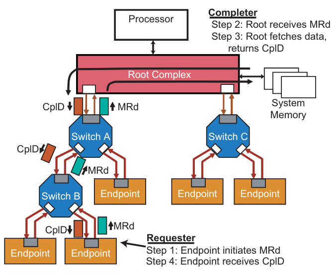
The request travels upstream through the PCIe fabric.
Each Switch examines the target address and simply forwards the packet toward the Root Complex.
No data is returned yet — this is just a “please fetch this address range” message.
3. Root Complex Fetches Data
When the Root Complex (or host bridge) receives the request:
It recognizes that the address corresponds to system memory.
It retrieves the requested data from DRAM.
4. Root Complex Sends Completion Packets
The data is returned in one or more Completion TLPs.
Each Completion contains:
The BDF of the original Requester (so it knows where to send it).
The same Tag that was in the request (so the Requester can match it).
Up to 4 KB of data per Completion (but often much smaller).
Completion Status bits (OK, Unsupported Request, Completer Abort, etc.).
5. Requester Matches the Response
The Requester receives the Completions and uses the Tag field to figure out which outstanding request this data belongs to.
This is important because multiple requests may be in flight simultaneously (PCIe supports split transactions).
6. Error Handling
If something went wrong (e.g., the memory address was invalid), the Completer sets error bits in the Completion Status field.
The software driver is then responsible for deciding what to do — log an error, retry, or halt.
Key Points
BDF (Bus, Device, Function) → acts as the Requester’s “return address.”
Tag field → acts like a “transaction ID” to keep track of which request is being completed.
Completions can be split → multiple TLPs may be required to deliver all the data.
Completion Status bits → provide error reporting back to the Requester.
Split Transactions → PCIe does not “stall” while waiting for data. The bus is free for other traffic while the Root Complex works on the memory access.