The interface between the MAC and PHY layers is known as the PIPE (PHY Interface for PCI Express) interface. It is:
- Dual-simplex
- Parallel bus–based
The Data Link Layer (DLL) logic interfaces directly with the MAC layer.
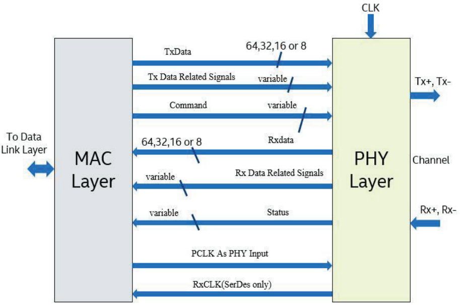
PIPE Data Interface
According to the PIPE 3.1 specification published by Intel, the following data widths are supported:
-
Conventional PIPE architecture:
- TxData / RxData widths: 8 / 16 / 32 / 64 bits per direction
-
SerDes architecture:
- TxData / RxData widths: 10 / 20 / 40 / 80 bits per direction
Control signals include:
- TxDataK (transmit)
- RxDataK (receive)
Each control (K) line corresponds to a byte of data and indicates whether the byte is a data symbol or a control symbol.
The PHY provides RxData synchronized to the recovered clock (RxClk), with the data width defined by RxWidth.
Command and Status Buses
Command Bus (MAC → PHY)
The command bus allows the MAC to control PHY operations, including:
- Receiver detection (TxDetectRx)
- Entry into external loopback mode
- Entry into electrical idle state (TxElecIdle)
- PHY reset (Reset)
- Power management state transitions (PowerDown)
Status Bus (PHY → MAC)
The status bus communicates PHY state information back to the MAC, including:
- Symbol lock acquisition
- Valid data indication on RxData (RxValid)
- Completion of power management state transitions
- Receiver detection status (PhyStatus)
- Detection of electrical idle on the link (RxElecIdle)
The PCLK signal is used to support synchronous data transmission between the MAC and PHY layers.