DLLPs (Data Link Layer Packets) are tiny, 8-byte control packets that:
- Travel only between two directly connected devices on a PCIe Link.
- Are never routed through Switches, nor passed up to the Transaction Layer.
- Are used for link management functions, including:
- Flow Control Updates (credits)
- Acknowledgements / NAKs
- Power Management Messages
Because they’re so small, they introduce minimal overhead while keeping the link reliable and synchronized.
🧠 DLLP Life Cycle
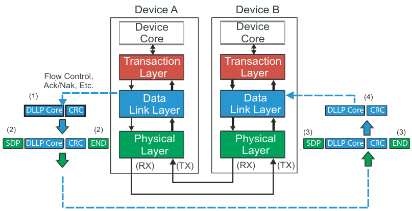
1. DLLP Assembly (Transmit Side)
- Starts at the Data Link Layer of the transmitter.
- DLLP Core (the 8-byte payload) is created (e.g., flow control update).
- A 16-bit CRC is appended for error detection.
- The Physical Layer then:
- Adds Start-of-Frame (STP) and End-of-Frame (END) characters (Gen1/Gen2)
- Encodes the bitstream (8b/10b for Gen1/Gen2, 128b/130b for Gen3+)
- Sends it across all lanes using differential signaling.
2. DLLP Disassembly (Receive Side)
-
The Physical Layer:
- Decodes the bitstream
- Removes STP/END framing characters
-
The resulting DLLP is forwarded to the Data Link Layer, which:
- Checks the CRC for errors
- Consumes the packet — it does not go up to the Transaction Layer
- Takes an action based on the DLLP type (e.g., update credit counters)
🎯 Key Points
- Transparent to Software: The Transaction Layer and software do not see DLLPs — everything is automatic.
- Always 8 Bytes: Small size = minimal bandwidth cost.
- Stay Local: Only exist between two directly connected devices.
- Essential for Reliability: DLLPs keep the link flow-controlled and error-free.