In this scenario, there are two enable signals, say:
aen1→ enables register 1aen2→ enables register 2
They are sequential — meaning aen2 is supposed to go high shortly after aen1, so that data moves smoothly through a two-stage pipeline.
However, both aen1 and aen2 are being:
- Generated in the source clock domain, and
- Sent across the clock domain boundary independently.
Each signal therefore passes through its own synchronizer into the receiving domain.
The core timing hazard:
Because of clock phase differences and slight timing skew between aen1 and aen2, there can be a tiny gap where:
aen1has already gone low, butaen2hasn’t yet gone high.
If the receiving clock edge happens right in that small window, the destination logic will see both signals low for one cycle — effectively breaking the enable chain.
➡️ The result:
A one-cycle bubble forms in the data pipeline — the data meant for the second stage (a2) is missed or delayed.
✅ The Solution — Consolidation + Extra Flip-Flop
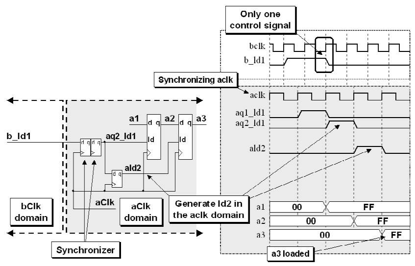
To prevent that “gap” condition, the safest and simplest method is:
1. Send only one control signal across the CDC boundary
- Combine the timing control into a single synchronized signal (e.g.,
aen1). - Do not attempt to send both
aen1andaen2across separately.
2. Regenerate the second (phase-shifted) signal locally
- Once
aen1is safely synchronized into the receiving domain,
generate the delayed or phase-shifted signal (aen2) inside the destination domain using one additional flip-flop.
In other words:
// In receiving clock domain
always @(posedge dest_clk) begin
     aen1_d <= sync_aen1;  // One-cycle delayed copy
 end
 assign aen2 = aen1_d;  // Second enable derived locally
Now both aen1 and aen2 are perfectly aligned to the same destination clock, so there’s no risk of a missing cycle.
🧠 Why This Works
- Only one CDC signal (
aen1) crosses the boundary → eliminates inter-signal skew. - The second phase (
aen2) is generated with a known one-cycle delay within the destination domain → guaranteed synchronization. - You maintain the intended sequencing, but with deterministic timing relative to the destination clock.
🏗️ Practical Example
💡 Key Takeaway
Always synchronize one control signal per timing event, and generate any required sequential or delayed control phases locally within the destination domain.
This principle not only prevents missing cycles but also greatly simplifies verification and timing closure.